For a MikroTik VLAN-aware switch, write the VLAN membership of every port, classify untagged ingress with the intended PVID, and keep a reachable path to the switch’s own management interface. A trunk carrying the right tags is only the Layer 2 path; the upstream router decides which routed connections pass.
Validation: documentation reviewed November 11, 2026. This is an illustrative RouterOS 7 switch configuration, not a tested device export. Record the actual model, RouterOS build, switch chip, ports and recovery access. Hardware offload support varies by chip and configuration; this guide does not promise a throughput result.
Give the switch and the router different jobs
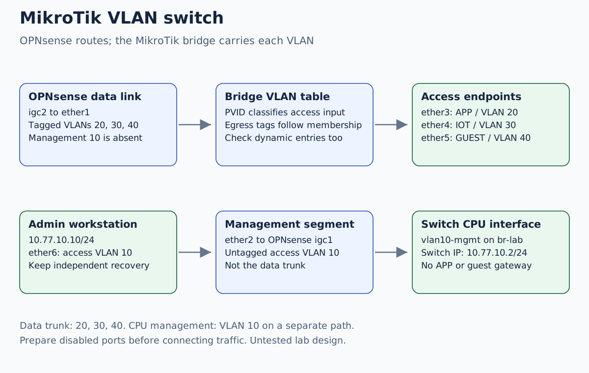
Our switch connects to the existing OPNsense VLAN design. OPNsense owns the four gateways; MikroTik switches their Ethernet traffic. Do not copy the gateways onto the switch as well.
| Segment | Subnet | Gateway on OPNsense | Example endpoint |
|---|---|---|---|
| MGMT, VLAN 10 | 10.77.10.0/24 | 10.77.10.1 | Admin 10.77.10.10; switch 10.77.10.2 |
| APP, VLAN 20 | 10.77.20.0/24 | 10.77.20.1 | Application 10.77.20.50 |
| IOT, VLAN 30 | 10.77.30.0/24 | 10.77.30.1 | DHCP .100–.149 |
| GUEST, VLAN 40 | 10.77.40.0/24 | 10.77.40.1 | DHCP .100–.149 |
These private addresses are a chosen lab plan. The selected switch needs at
least six verified spare ports. No existing port is silently removed from a
factory bridge. A port can belong to only one bridge; adapt an existing
configuration through its own migration plan instead of running these add
commands over it.
Make a port matrix before a configuration
| Port | Connection | Tagged egress | Untagged egress / ingress PVID |
|---|---|---|---|
| ether1 | OPNsense data port igc2 | 20, 30, 40 | None; admit tagged ingress only |
| ether2 | OPNsense management port igc1 | None | 10 |
| ether3 | Application server | None | 20 |
| ether4 | IoT test endpoint | None | 30 |
| ether5 | Guest test endpoint | None | 40 |
| ether6 | Admin workstation | None | 10 |
| Bridge CPU interface | Switch management VLAN interface | 10 | None in this design |
VLAN 10 is absent from the data trunk. The switch’s CPU participates in VLAN 10 because its management IP lives there; it needs no APP, IOT or GUEST IP. The separate ether2 link is ordinary untagged management Ethernet at OPNsense. Do not bridge OPNsense’s management and data ports together.
Export the existing configuration and create a protected off-device backup using the safe-change workflow. Have a tested console or other independent recovery path. Safe Mode is useful for bounded changes, but it is not an unlimited backup or an instant guarantee of recovery after every kind of failure.
Prepare an isolated bridge with its ports disabled
Use only an isolated lab device with the selected data cables disconnected. While VLAN filtering is off, a connected bridge can join traffic that should remain separated. The candidate below keeps every added port disabled until the table is complete; do not enable the ports early to test connectivity.
/interface bridge add name=br-lab vlan-filtering=no protocol-mode=rstp comment="Boxvirt M01 lab bridge"
/interface bridge port add bridge=br-lab interface=ether1 disabled=yes ingress-filtering=yes frame-types=admit-only-vlan-tagged comment="Boxvirt M01 data uplink"
/interface bridge port add bridge=br-lab interface=ether2 disabled=yes pvid=10 ingress-filtering=yes frame-types=admit-only-untagged-and-priority-tagged comment="Boxvirt M01 MGMT uplink"
/interface bridge port add bridge=br-lab interface=ether3 disabled=yes pvid=20 ingress-filtering=yes frame-types=admit-only-untagged-and-priority-tagged comment="Boxvirt M01 APP"
/interface bridge port add bridge=br-lab interface=ether4 disabled=yes pvid=30 ingress-filtering=yes frame-types=admit-only-untagged-and-priority-tagged comment="Boxvirt M01 IOT"
/interface bridge port add bridge=br-lab interface=ether5 disabled=yes pvid=40 ingress-filtering=yes frame-types=admit-only-untagged-and-priority-tagged comment="Boxvirt M01 GUEST"
/interface bridge port add bridge=br-lab interface=ether6 disabled=yes pvid=10 ingress-filtering=yes frame-types=admit-only-untagged-and-priority-tagged comment="Boxvirt M01 admin"
This is an added lab bridge, not a replacement for /export. Names, port
ownership and unique comments must be checked before adding anything. Keep
unselected ports disconnected and outside this experiment.
Add VLAN membership and the CPU management interface
/interface bridge vlan add bridge=br-lab vlan-ids=10 tagged=br-lab untagged=ether2,ether6 comment="Boxvirt M01 MGMT membership"
/interface bridge vlan add bridge=br-lab vlan-ids=20 tagged=ether1 untagged=ether3 comment="Boxvirt M01 APP membership"
/interface bridge vlan add bridge=br-lab vlan-ids=30 tagged=ether1 untagged=ether4 comment="Boxvirt M01 IOT membership"
/interface bridge vlan add bridge=br-lab vlan-ids=40 tagged=ether1 untagged=ether5 comment="Boxvirt M01 GUEST membership"
/interface vlan add name=vlan10-mgmt interface=br-lab vlan-id=10 comment="Boxvirt M01 CPU management"
/ip address add address=10.77.10.2/24 interface=vlan10-mgmt comment="Boxvirt M01 switch address"
The bridge interface in the tagged list is the CPU path, not another physical trunk. Current RouterOS builds can also create dynamic VLAN entries in some cases. Inspect the effective table; do not assume every displayed row came from a command in this article.
This management address reaches local management peers without adding a default route. If the switch itself needs remote DNS, time or update services, review its management gateway and policy separately. Restrict IP services, neighbor discovery and MAC management through the existing input and management guide.
Only after the complete table and recovery path are reviewed, enable VLAN filtering on this new, isolated bridge:
/interface bridge set [find where name=br-lab] vlan-filtering=yes
All six added ports remain disabled. First enable only the uniquely identified
management uplink and admin port in the lab UI. Connect the intended cables,
verify admin addressing, and open a fresh session to 10.77.10.2. Then enable
the data uplink and one endpoint port at a time, comparing each with the
matrix. Do not use a bulk enable across every bridge port.
Inspect membership before blaming routing
/interface bridge print detail where name=br-lab
/interface bridge port print detail where bridge=br-lab
/interface bridge vlan print detail where bridge=br-lab
/interface bridge host print where bridge=br-lab
/ip address print where interface=vlan10-mgmt
From an access endpoint, expect ordinary untagged Ethernet and an address in its VLAN’s subnet. Do not add an endpoint VLAN subinterface as well. On the uplink, expect the corresponding tag. Record hardware-offload flags for the actual chip, but do not treat one flag as proof of performance or isolation.
A lease failure should lead to link, PVID, VLAN membership and upstream DHCP checks. A correct lease followed by an application denial should lead to the router’s policy and the application’s listener/return route. The switch is not responsible for creating a DHCP scope merely because it carries VLAN 30.
Verify access and recover through the independent path
Test the known HTTPS application from the permitted IoT client, then from the guest that should be denied. Correlate the latter with the OPNsense rule decision. Also open fresh switch and firewall management sessions from the admin workstation and confirm guest access to them is denied.
A VLAN tag is not a routed firewall rule, and devices in one VLAN may talk without crossing the router. IPv4 checks alone do not establish IPv6 isolation; the complete network needs its own IPv6/RA policy and tests.
For an AP carrying management plus IoT and guest SSIDs, continue with the WiFi CAPsMAN walkthrough. Its AP uplink has a different allowed-VLAN list from the firewall data trunk.
If a change breaks management, stop enabling ports. Use the retained console to restore the recorded configuration; keep data ports disconnected while repairing the VLAN table. Do not disable VLAN filtering on a connected live bridge as an improvised recovery step that joins the isolated segments.