Before configuring MikroTik CAPsMAN, identify the AP’s wireless package and choose its matching controller family. Then decide where client traffic is forwarded. An AP appearing on the controller proves neither its VLAN path nor the intended firewall policy.
Validation: documentation reviewed November 11, 2026. This is a selected WiFi CAPsMAN lab design, not a tested AP configuration. The worked path uses a separate controller and one wifi-qcom, Wi-Fi 6 AP, local forwarding and one 5 GHz radio. Record the actual device models, RouterOS/package builds and radio MAC. Wi-Fi 7 MLO, roaming between APs and legacy wireless migration are outside this example.
Choose the package family before copying a menu path
| AP package / menu | Controller family | Important boundary |
|---|---|---|
wireless, /interface wireless | Legacy /caps-man | Separate controller family from this guide |
wifi-qcom, /interface wifi | WiFi CAPsMAN | Selected AP family; verify its actual model support |
wifi-qcom-ac, /interface wifi | WiFi CAPsMAN | Different VLAN handling; do not copy qcom datapath VLAN configuration blindly |
The new WiFi menu also covers other packages in the current documentation;
this table deliberately selects a narrower example. An AP’s model suffix or
RouterOS major version alone does not establish the driver actually installed.
Inspect /system package print and the available interface menu on each device.
The official documentation distinguishes wifi-qcom-ac from wifi-qcom
datapath VLAN assignment and forwarding support. It also distinguishes local
and CAPsMAN forwarding. An old assertion that the new controller can only
forward locally is not a safe rule for every current package/build.
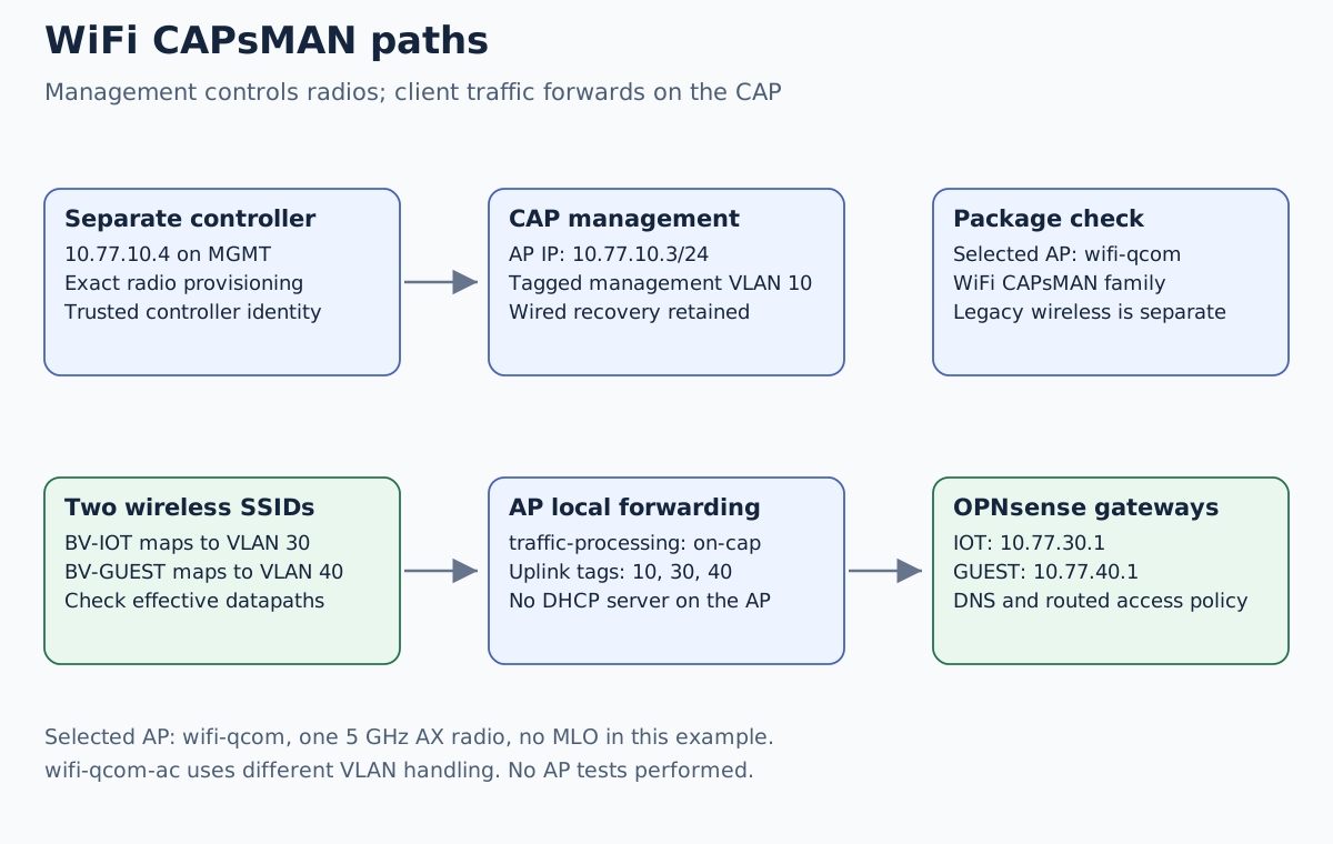
We choose traffic-processing=on-cap explicitly. Client packets leave through
the AP’s Ethernet uplink; the controller is not the chosen data gateway.
Keeping that decision explicit makes the uplink VLAN test meaningful.
Carry management and both SSIDs to their actual gateways
Our existing OPNsense gateway plan uses management VLAN 10, IoT VLAN 30 and guest VLAN 40. A MikroTik switch carries those segments to the AP.
| Role | Private lab value |
|---|---|
| Controller | 10.77.10.4/24, on the management segment |
| AP management | 10.77.10.3/24, VLAN 10 |
| OPNsense management gateway | 10.77.10.1 |
| IoT SSID | BV-IOT, VLAN 30, gateway 10.77.30.1 |
| Guest SSID | BV-GUEST, VLAN 40, gateway 10.77.40.1 |
| AP uplink | Tagged VLANs 10, 30 and 40 |
| Client DHCP | Provided by OPNsense; no new DHCP server on AP/controller |
The AP needs a spare switch port configured for this tagged uplink. In the switch design, VLAN 10 must reach the management segment, and VLANs 30/40 must reach the OPNsense data trunk. Do not assume the AP’s uplink has the same allowed VLAN list as the firewall data port, which deliberately excludes 10.
The MikroTik VLAN switch guide defines that separate management and data path before adding wireless clients.
Management on VLAN 10 must already work before starting radio provisioning. Review the selected AP’s local bridge, CPU management interface and Ethernet membership. The AP must have a reachable management address on VLAN 10 rather than depending on a DHCP server accidentally created on an SSID.
The existing OPNsense VLAN guide describes the gateway side; its firewall policy example defines routed permissions. Keep a protected export/backup and wired recovery access to both MikroTik devices before changing their management or radio state.
Prepare two configurations and one disabled provisioning rule
Create unique security profiles for IoT and guest clients through the installed WiFi UI. Use separate strong passphrases that are not reused for administration. Select the actual deployment country and legal radio settings. Review WPA2/WPA3 compatibility for the real clients rather than promising that every IoT device supports the same authentication method.
For the selected wifi-qcom AP, prepare these controller-side objects:
| Object | Name | Settings for this design |
|---|---|---|
| Datapath | bv-iot | VLAN ID 30; traffic processing on-cap |
| Datapath | bv-guest | VLAN ID 40; traffic processing on-cap |
| Configuration | bv-iot5 | AP mode, SSID BV-IOT, selected country, IoT security profile, bv-iot |
| Configuration | bv-guest5 | AP mode, SSID BV-GUEST, selected country, guest security profile, bv-guest |
| Provisioning | One new disabled rule | Exact observed radio MAC, supported band 5ghz-ax, master bv-iot5, slave bv-guest5 |
Use a radio-specific match during the first test; do not create a catch-all rule that reprovisions every existing AP. Existing matching static interfaces and earlier provisioning rules also affect the outcome. Inspect them before enabling the new candidate.
On the CAP, define its local datapath against the already reviewed AP bridge.
Assign it to the selected physical WiFi interface, set that interface’s
configuration manager to CAPsMAN, and set the CAP’s slaves-datapath to the
same local datapath so virtual interfaces join the intended local bridge.
Keep the selected radio disabled until control and datapath settings are
reviewed. Do not pass configuration.manager through the controller profile;
it is a local CAP decision.
In the CAP configuration, select its VLAN 10 management interface for
discovery and specify controller address 10.77.10.4. Restrict the controller
service and its management firewall permissions to the intended management
path. Explicit addressing avoids discovering an unrelated controller; it does
not replace authentication. Follow the installed version’s certificate
enrollment, trusted controller identity and peer-certificate controls on a
trusted wired management network. Do not expose provisioning to WAN.
Join one AP and inspect effective settings
Enable the chosen controller/CAP services through their supported UI after reviewing existing users and settings, then enable only the radio-specific provisioning rule and selected radio. Do not restart a shared controller just to apply one profile without considering the other APs.
These are read-only candidate inspection commands on the relevant devices:
/system package print
/interface wifi radio print detail
/interface wifi print detail
/interface wifi registration-table print detail
On the controller, match the expected radio MAC, AP identity and profile.
On the AP, inspect the effective bridge and VLAN behavior of both the master
and virtual interface. For wifi-qcom, the selected datapath supplies the
SSID’s VLAN ID; confirm the expected tag on Ethernet. If the AP uses bridge
VLAN filtering, its actual wireless and uplink membership must also admit
those frames. Record that runtime membership before accepting the design.
Do not transplant the manual bridge-PVID workaround for wifi-qcom-ac into
this qcom example or assume dynamically created WiFi interface names are
stable. Use the installed driver’s documented configuration path. Keep unused
Ethernet ports disabled/disconnected until their VLAN roles are reviewed.
Test the clients after provisioning
Join one disposable client to each SSID and record its actual address,
gateway, DNS server and assigned VLAN. For this lab, IoT should receive an
address in 10.77.30.0/24; guest should receive one in 10.77.40.0/24.
A visible SSID and a successful WiFi association do not establish either fact.
| Flow | Intended result |
|---|---|
| Admin → controller and AP management | Fresh permitted management session |
| IoT client → own gateway DNS | Correct DNS response |
| Guest client → own gateway DNS | Correct DNS response |
| IoT → selected APP HTTPS exception | Application identity/content |
| Guest → APP and management | Matching routed-policy denial |
Repeat applicable tests over IPv6 before claiming dual-stack isolation. Same-SSID client isolation is a separate AP policy: a routed firewall cannot control packets that never reach it. If wireless clients must not talk to each other, specify and test the relevant client-isolation behavior as well.
If the AP joins but clients receive no lease, inspect profile/datapath, uplink tags, switch membership and upstream DHCP before changing controller keys. If clients get the wrong subnet, inspect the actual tag path and rogue DHCP offers. If leases are right but access is wrong, inspect router policy and the target service.
Change profiles without unnecessary reprovisioning
The official documentation warns that manual provisioning can recreate interfaces and break references. A profile edit does not automatically require deleting and recreating the radio’s interfaces. Recheck effective settings and client behavior after the smallest supported change.
For rollback, disable only the new provisioning candidate and affected radio or virtual SSID through wired management, then restore the recorded profile, CAP-local datapath and switch-port settings. Recheck a fresh admin session. An AP configuration restore does not undo an upstream switch change.