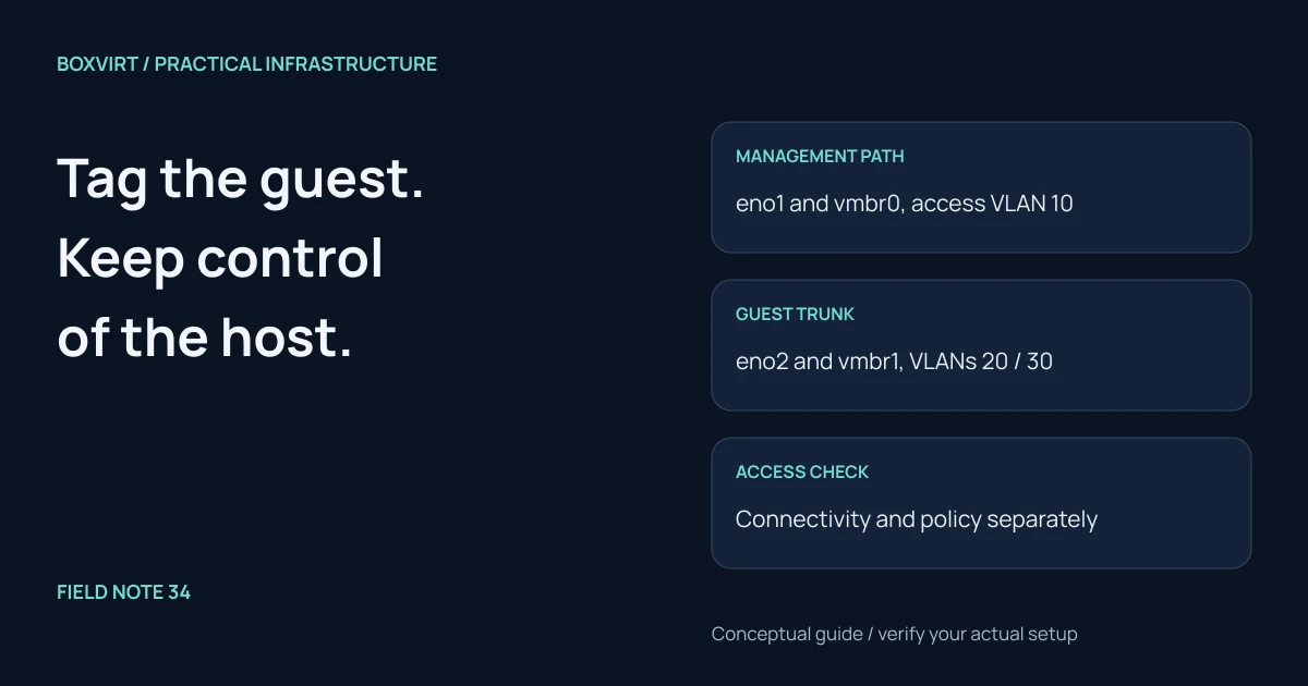
To connect Proxmox guests to VLANs, make the path agree from the VM’s NIC through the Linux bridge and physical switch to the VLAN’s gateway. For an ordinary access-style guest, set its VLAN tag in Proxmox and leave the guest’s interface untagged. Keep management reachable while testing both connectivity and the router’s intended isolation policy.
This worked design uses two wired uplinks: one existing management path and one new VLAN-aware guest bridge. It avoids migrating management onto a new trunk during the same change. A one-NIC host or a guest receiving a VLAN trunk needs a different design; use the networking overview to choose that design first.
Validation: documentation reviewed November 10, 2026. The topology below is an illustrative lab, not a tested switch or PVE configuration. Record the exact PVE build, switch firmware, router policy and port identities before rehearsing it. No live networking changes were made while preparing this article.
Draw management and guest traffic separately
| Purpose | PVE interface/path | Switch configuration | Address plan |
|---|---|---|---|
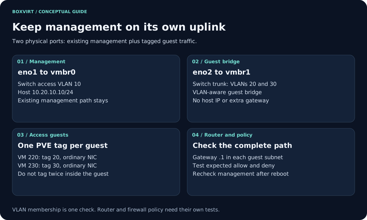
| Existing management | eno1 → vmbr0 | Access port in VLAN 10; frames untagged on the wire | Host 10.20.10.10/24, gateway 10.20.10.1 |
| Guest uplink | eno2 → vmbr1 | Trunk permitting tagged VLANs 20 and 30 | No host IP or gateway on vmbr1 |
| Application guest | VM 220 NIC on vmbr1, PVE tag 20 | Reaches VLAN 20 through the trunk | 10.20.20.40/24, gateway 10.20.20.1 |
| Test guest | VM 230 NIC on vmbr1, PVE tag 30 | Reaches VLAN 30 through the trunk | 10.20.30.40/24, gateway 10.20.30.1 |
These private addresses are chosen examples. The router must already have the two guest VLAN interfaces, addresses and intended policies. A Linux bridge does not create an upstream router, DHCP scope or DNS service.
On the switch, record the management access port, guest trunk port and router uplink. The router uplink must carry the selected guest VLANs too. Do not rely on the word “trunk” to mean that every switch permits the same VLAN list or uses the same untagged/native behavior.
For the guest trunk, reject untagged ingress where the switch supports it, or assign it to a deliberately unused isolated native VLAN. Do not make that port’s native VLAN the management VLAN 10. Record the actual PVID/native behavior at both ends; the two-line bridge VLAN excerpt alone does not prove that every untagged frame is rejected.
Save recovery access before adding the bridge
Keep a working console and save the existing host network configuration, included files, switch-port settings and affected VM NIC settings. Store the copy securely where it remains reachable if this host loses networking. Test the current management session from a second client before changing anything.
Match eno1 and eno2 to the physical ports. Never select an uplink merely
because another guide uses that name. Confirm that vmbr1 is unused and that
the proposed guest port is not part of an existing bond or bridge.
The existing management bridge remains in place. The following is an added
excerpt for the verified spare uplink, not a replacement for the complete
/etc/network/interfaces file:
iface eno2 inet manual

auto vmbr1
iface vmbr1 inet manual
    bridge-ports eno2
    bridge-stp off
    bridge-fd 0
    bridge-vlan-aware yes
    bridge-vids 20 30
Use the PVE GUI to add and review the Linux bridge where possible. Confirm the
intended VLAN list and absence of a new host gateway. The
official network guide
explains the supported Apply Configuration/ifupdown2 workflow. Apply only with
the saved configuration and console available. Bouncing a working bridge with
ifdown can interrupt guests and is not a harmless substitute.
Assign one access VLAN to each guest
With the disposable VM stopped, select its intended NIC, bridge vmbr1,
VirtIO model and VLAN tag 20 for VM 220. VM 230 uses tag 30. Review
the existing MAC, firewall option and link state rather than replacing the
whole NIC definition with a short example command.
Inside these Linux guests, configure the ordinary interface such as ens18.
Do not also create ens18.20 for VM 220: this example uses PVE to apply the
access VLAN. Trunk-to-guest designs deliberately do something else and need
an explicit allowed-VLAN and guest-subinterface plan.
| Boundary for VM 220 | Expected representation |
|---|---|
| Inside guest | Ordinary untagged Ethernet on ens18 |
| PVE guest-port configuration | VLAN tag 20 on vmbr1 |
Physical eno2 / switch trunk | VLAN 20 tagged |
| Router’s VLAN 20 interface | Gateway for 10.20.20.0/24 |
This matrix describes the intended external path. Firewall backends can add other virtual devices; do not hard-code one tap/firewall-bridge chain as the only valid runtime layout.
Check each segment before testing internet access
On the lab PVE host, inspect the stopped/started guests and bridge:
qm config 220
qm config 230
ip -br link
bridge link show
bridge vlan show
Compare the NIC’s bridge/tag/link settings and runtime membership with the matrix. Interpret the actual device names for the installed firewall backend. The bridge manual documents VLAN membership inspection.
From each guest, check its address, route, neighbor resolution and a service on its own VLAN. Then test its gateway and the intended external service. A DHCP failure should lead to scope, tag and broadcast-path checks, not arbitrary changes to the host’s own default gateway.
Verify policy and management independently
Define the expected results before testing:
| Flow | Expected in this illustrative policy |
|---|---|
| Trusted management client → PVE HTTPS | Allowed |
| VM 220 → its gateway and DNS | Allowed |
| VM 230 → its gateway and DNS | Allowed |
| VM 230 → VM 220 application TCP port | Denied unless a specific exception exists |
| Either guest VLAN → PVE management | Denied by the intended management policy |
Use a known listening service and both a positive and negative control. Unanswered ping alone does not prove isolation. Repeat applicable tests over IPv6; a successful IPv4 deny test says nothing about an untested IPv6 path. Use the firewall guide for access rules. VLAN membership and firewall permission are separate checks.
Finally, open a fresh management session, then rehearse a planned reboot and repeat the matrix. If access fails, use the console to restore the saved host configuration through the supported workflow and restore affected switch settings too. A host rollback cannot undo a switch change. Keep the guests stopped or disconnected until their segment and policy are understood.