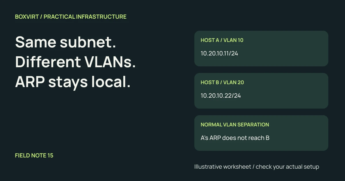
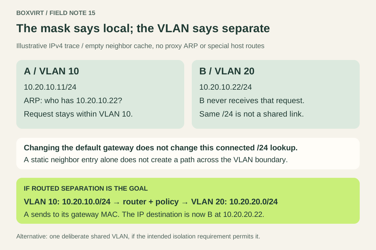
Two hosts can have addresses inside the same IPv4 /24 and still be unable to reach each other because they belong to different VLANs. In an ordinary Ethernet design, each thinks the other is on its own link, so it tries ARP for the destination. The VLAN boundary prevents that request from reaching the other host.
The repair depends on the intended relationship. Put hosts in one deliberate layer-2 segment if they should share a LAN, or use distinct IPv4 subnets and an explicit routing policy if they should remain in separate VLANs. Changing only the default gateway does not correct the direct-delivery decision in this example.
This guide traces an illustrative IPv4 failure. It assumes normal VLAN-aware switching, no proxy ARP, no special host routes and no cross-VLAN layer-2 interconnection. It is not a packet capture or a tested switch configuration.
Start with the two host configurations
Consider two guest NICs connected through a correctly VLAN-filtered path:
| Setting | Host A | Host B |
|---|---|---|
| IPv4 address | 10.20.10.11/24 | 10.20.10.22/24 |
| VLAN membership | 10 | 20 |
| Calculated IPv4 network | 10.20.10.0/24 | 10.20.10.0/24 |
| Intended test | Connect to B’s service | Receive A’s connection |
The addresses are illustrative private addresses. Host A’s mask makes .22
look on-link. The local/remote decision in RFC 1122
explains the ordinary mask-based distinction between direct delivery and use of
a gateway. Here the two hosts agree on an IPv4 network number, but the switching
configuration gives them different link-layer domains.
Keep VLAN ID, IPv4 prefix and firewall policy as separate worksheet columns. None can be inferred from the other. VLAN 20 does not automatically mean the address range must contain the decimal number 20; we will use that convention later only to make the example easy to read.
Follow the first unresolved neighbor
Assume A has no usable neighbor-cache entry for B:
- A selects its connected
10.20.10.0/24route for destination10.20.10.22. - It needs B’s Ethernet address, so it sends an ARP request asking who owns
.22. - The request is broadcast within VLAN 10. Correct VLAN separation does not deliver that broadcast to B’s port in VLAN 20.
- B cannot answer a request it never receives. A cannot construct the ordinary destination frame for the application connection.
RFC 826 describes resolving a protocol address to an Ethernet address on the connected link. A manually inserted neighbor entry would not, on its own, create a forwarding path between these VLANs. An old entry can change what you observe, which is why the trace states its empty-cache assumption explicitly.
The Linux kernel’s bridge documentation describes VLAN-aware forwarding: the destination MAC and VLAN context matter. The same physical uplink can carry both VLANs without merging them. Conversely, a bridge that is not configured to enforce VLAN membership cannot be assumed to provide the separation merely because someone assigned VLAN names.
Why the default gateway does not rescue this packet
For this destination, A’s ordinary lookup chooses a connected route. A default
route is for destinations without a more specific match; assigning a different
default gateway does not tell A that .22 moved to VLAN 20.
Likewise, adding a broad inter-VLAN firewall allowance is not evidence that the initial request reaches a router. First identify the selected next hop. In this example the failure occurs before normal inter-subnet forwarding can take place. A host firewall can cause other symptoms, but it does not join the broadcast domains or correct the addressing assumption.
Some intentional designs use proxy ARP, host routes, separate routing instances or other mechanisms to handle repeated address space. Those mechanisms change the assumptions and need their own address-ownership and return-path design. The problem is not a universal claim that repeated prefixes can never exist. It is that an ordinary routed-LAN recipe does not supply those extra mechanisms.
Choose between a shared segment and routed separation
If the two machines belong in one LAN, align their intended VLAN membership through the entire path. Check virtual ports, physical access ports and allowed tags on trunks. This deliberately changes their layer-2 relationship; confirm that it matches the isolation requirement before moving either NIC.
If they should remain separate, an illustrative routed plan is:
| Setting | VLAN 10 | VLAN 20 |
|---|---|---|
| Subnet | 10.20.10.0/24 | 10.20.20.0/24 |
| Example host | A: 10.20.10.11/24 | B: 10.20.20.22/24 |
| Example router interface | 10.20.10.1/24 | 10.20.20.1/24 |
A now recognizes 10.20.20.22 as outside its connected /24 and sends the packet
to its router’s Ethernet address. Its IP destination remains B. The router needs
both networks reachable and a policy allowing the required service; B needs a
return route through its gateway. Separate private LANs do not inherently require
NAT between them.
For example, the intended policy might permit A to reach B over TCP 443 while denying other new connections. That is a chosen acceptance target, not a rule installed by this worksheet. Verify stateful replies and test a denied operation as well as the permitted one. Subnet separation alone is not an access policy.
Trace the VLAN path through Proxmox and the switch
In Proxmox, map the guest NIC, its bridge, the bridge uplink and the physical switch port. The official Proxmox network documentation explains the guest-tag and trunk models. A guest assigned a VLAN tag at its Proxmox virtual port normally sees an untagged interface for that VLAN; a guest expected to manage multiple VLANs needs a deliberately different trunk design.
Do not assume that adding the same tag inside the guest repairs a mismatch. Record where tags are added or removed and which VLANs every link permits. An allowed VLAN on the switch but absent from the bridge path still fails. An accidental untagged/native mapping can put a NIC in a different domain than its configuration label suggests.
The Proxmox networking guide covers bridge and uplink planning. Use this article’s packet trace to ask one narrower question: does the destination’s actual layer-2 location agree with what the sender’s address and mask imply?
Collect evidence before making a network change
Use the affected host’s route lookup and neighbor table to inspect the original
case. On Linux, ip route get 10.20.10.22 shows the selected path; the
ip-route manual
explains that lookup. A connected-device result is not proof that B is present
on that segment. An unresolved neighbor entry is a clue, not a unique diagnosis:
a stopped host, bad port membership or filtering can produce similar evidence.
Record these observations for the actual layout:
| Evidence | Question it answers |
|---|---|
| Address and prefix on both hosts | Does each host classify the other as on-link? |
| Selected route and next hop | Is the sender trying direct delivery or the gateway? |
| Neighbor state and authorized link observation | Is resolution attempted in the expected VLAN, and is there a reply? |
| Guest-to-uplink membership map | Do bridge and switch agree about the VLAN? |
| Application and denied-flow checks | Does the resulting routing policy meet the intended relationship? |
Keep console access and a copy of the relevant host and switch settings before changing management VLANs. A host-only rollback does not undo a switch-port change. Make the addressing and membership change through your platform’s supported workflow, then repeat the route, neighbor and application checks.
The four-VLAN VLSM example helps allocate distinct prefixes. Check each candidate with the IPv4 subnet calculator, then document which flows are allowed between the resulting networks. This IPv4 ARP trace does not describe IPv6 neighbor discovery; IPv6 needs its own addressing and policy review.