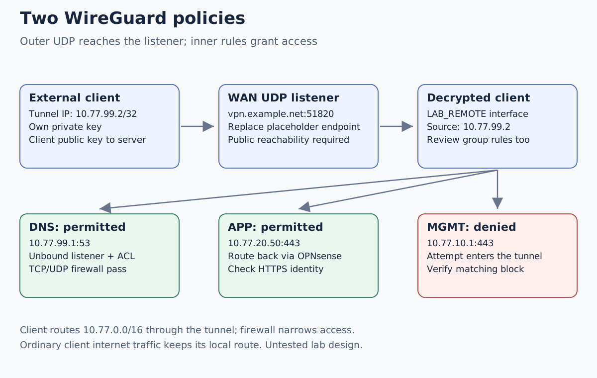
An OPNsense WireGuard remote-access connection needs two separate permissions: UDP reaching the firewall’s WireGuard listener, and decrypted client traffic reaching its allowed destinations. A handshake checks the first part; prove the second with an application request, a DNS query and a deliberately denied connection.
This example routes a private lab range through the tunnel while ordinary internet traffic stays on the client’s existing connection. Firewall rules permit only one HTTPS application and DNS. Validation: Documentation reviewed November 11, 2026; the tunnel and tests below have not been run. Record the installed OPNsense build, rule implementation, client version and actual WireGuard device name. The guide is an IPv4 example, not a full-tunnel or site-to-site recipe.
Check whether an external client can reach the listener
Use a separate client outside the home LAN, such as a laptop using a mobile connection. Confirm that OPNsense has reachable public IPv4 or that an upstream router you control can forward the chosen UDP port to it. Carrier-grade NAT cannot be solved just by adding a rule on OPNsense.
Our endpoint name, vpn.example.net, is a documentation placeholder. Replace
it with a name you control that resolves to the actual reachable address;
check the resolution from outside. For double NAT, document each translation
and ensure the upstream UDP mapping reaches the OPNsense WAN address. Never
publish the management GUI to solve a VPN reachability problem.
Export a protected configuration off the firewall and confirm console access. Plan changes to one new instance; restarting a shared WireGuard service can interrupt other users.
Give addresses and keys distinct roles
| Item | Value in this private lab |
|---|---|
| New instance description | LAB_REMOTE |
| Instance tunnel address | 10.77.99.1/24 |
| One remote client’s tunnel address | 10.77.99.2/32 |
| Server peer Allowed IPs for this client | 10.77.99.2/32 |
| Client routes through its server peer | 10.77.0.0/16 |
| Application | 10.77.20.50, TCP 443, app.home.arpa |
| Resolver used by client | 10.77.99.1, TCP/UDP 53 |
| Management negative-control target | 10.77.10.1, TCP 443 |
The client’s route includes all example lab subnets, including the tunnel
address. It is deliberately broader than the permitted services: the firewall
enforces access. This also makes a management-denial test meaningful, because
that attempt actually enters the tunnel. Do not use this /16 if it overlaps
the remote client’s local network or another VPN.
On the server, this remote user’s peer gets only its unique tunnel /32.
It must not claim the lab’s LAN networks as networks behind the client.
For the difference between route selection and source ownership, see
WireGuard AllowedIPs.
Generate a separate key pair on each side. Exchange public keys only; keep private keys on their owning devices. An exported client file or QR code contains credentials and needs the same protection as a private key.
Create the instance, peer and interface assignment
Under VPN → WireGuard → Instances, create the new instance with a unique
UDP listen port, such as 51820 if it is unused, and tunnel address
10.77.99.1/24. Generate its keys and record its public key. Leave the
instance’s advanced DNS Server field empty: it is not the field for telling
the remote client which resolver to use. Keep route creation enabled for this
directly connected lab design.
Under VPN → WireGuard → Peers, add the remote client’s public key and
Allowed IPs 10.77.99.2/32. A roaming client’s server-side endpoint can remain
unspecified. Associate that peer with the new instance. Review the selected
peer carefully if other users already exist.
Assign the actual wg device under Interfaces → Assignments, enable it
and describe it as LAB_REMOTE. Set its IPv4 and IPv6 configuration types
to None; the instance supplies its tunnel address. Enable/apply WireGuard
through the documented General workflow and confirm the actual assignment.
Do not guess wg0 or wg1 from another installation.
For MTU, start from the documented value appropriate to the real outer path. The currently documented ordinary Ethernet example uses 1420; a lower WAN MTU needs reconsideration. If small requests work but larger transfers stall, inspect path MTU and the documented normalization/MSS controls. A guessed universal MSS value can conceal the wrong diagnosis.
Permit the handshake and narrowly permit the inner traffic
Review disabled candidate rules first. For this IPv4 lab, use incoming, quick, stateful rules with source port any:
| Incoming interface | Source | Destination | Protocol / destination port | Action |
|---|---|---|---|---|
| WAN | Remote public address if stable; otherwise any | WAN address | UDP / selected listener port | Pass |
| LAB_REMOTE | 10.77.99.2/32 | 10.77.99.1 | TCP/UDP / 53 | Pass |
| LAB_REMOTE | 10.77.99.2/32 | 10.77.20.50 | TCP / 443 | Pass |
| LAB_REMOTE | 10.77.99.2/32 | 10.77.0.0/16 | Any | Block; log for the test |
The two inner passes precede the block. Inspect floating/group rules and any existing WireGuard-group allow that might decide the connection first. The WAN UDP permission does not permit the inner client to reach every LAN.
Unbound must listen on the tunnel address and permit the tunnel client in its access controls. Check its effective access lists; reload it after the new interface appears if needed by your configuration. Do not expose resolver port 53 on WAN to make tunnel DNS work.
Use the Unbound DNS walkthrough to establish the service record and distinguish an explicit resolver query from the client’s normal DNS selection.
The application is directly behind OPNsense and uses 10.77.20.1 as its
gateway. It therefore has a return path to 10.77.99.2 through the firewall.
If another router is its gateway, document the required return route there.
This example needs no added source NAT between tunnel and APP. Interface
assignment may generate outbound NAT for other cases; that does not create
an application permission or make this a full-internet tunnel.
Configure the client without moving its internet default route
On the client, use the installed application’s equivalent fields:
[Interface]
PrivateKey = <CLIENT_PRIVATE_KEY_ON_THIS_DEVICE>
Address = 10.77.99.2/32
DNS = 10.77.99.1

[Peer]
PublicKey = <OPNSENSE_INSTANCE_PUBLIC_KEY>
Endpoint = vpn.example.net:51820
AllowedIPs = 10.77.0.0/16
PersistentKeepalive = 25
The angle-bracket values and endpoint are placeholders; this file is not import-ready. Keepalive is useful when a NAT mapping must remain usable; it is not a fix for missing routes or firewall permissions. Set client MTU consistently with the reviewed path where the client requires an explicit value.
There is no 0.0.0.0/0 route here. Ordinary internet traffic keeps using the
client’s normal connection. However, the client app’s DNS field may change
DNS for the whole device, depending on its platform. Do not promise split DNS
just because traffic routing is split. This example needs the tunnel resolver
to answer the public names that the client actually sends to it, too.
Test the service, the name and the denied path
From the external lab client with the tunnel active, check the latest handshake and data counters on both ends. Then query the intended resolver explicitly:
dig @10.77.99.1 app.home.arpa A
dig +tcp @10.77.99.1 app.home.arpa A
curl --connect-timeout 5 --max-time 15 https://app.home.arpa/
The DNS record must exist and point at 10.77.20.50. The HTTPS service needs
a certificate covering the name and a trusted chain on this client; do not
disable certificate checks. Record the expected application marker rather
than accepting any generic web page as success.
| Check | Intended result |
|---|---|
| Public endpoint UDP reaches listener | Recent handshake with the intended peer |
| Explicit A query through tunnel | Application address |
| Application HTTPS | Expected service identity/content |
New connection to 10.77.10.1:443 | Matching LAB_REMOTE block decision |
| Client’s ordinary internet route | Remains on its local connection |
| Tunnel disabled | Private lab application no longer reachable by this route |
Verify the actual route for the negative-control target and correlate the attempt with firewall evidence. A timeout caused by an overlapping hotel LAN does not prove the tunnel policy denied management access.
Diagnose and revoke one client
With no handshake, inspect endpoint resolution, upstream NAT, listener port,
WAN rule and keys. With a handshake but no application, inspect client route,
server peer /32, inner rule order, application listener and return route.
If IP access works but the name fails, inspect client resolver selection and
Unbound listener/ACL/record. With failures only on larger transfers, examine
MTU and TCP MSS using the actual path.
To revoke this user, disable/remove its peer and apply the change, then verify that the client cannot establish a new usable tunnel. Review and remove only affected test states if immediate session termination requires it. Other clients’ peers must remain enabled. If a private key was exposed, replace the affected key pair and remove the old peer identity.
For rollback, remove the new client route/profile and revert the recorded instance, assignment, DNS and rule changes through the retained management path. If management is lost, use the console and known-good configuration.